
I began by creating a mathematical model for a scaled-down prototype of the UAV system to verify the control laws safely. In the "PLANT" subsystem, you can see I utilized a mass of 0.2 kg (represented by the 1/0.2 gain block) and a rotational inertia of 0.1 (the 1/0.1 block). For the vertical axis, I calculated acceleration by taking the thrust input, dividing it by this prototype mass, and subtracting gravity. For the horizontal axis, I modeled the relationship between torque and tilt angle. Even though the final unit will be 2 meters wide, simulating this lightweight test model first allows us to isolate and validate the relationship between thrust, gravity, and acceleration without the complexity of heavy-lift aerodynamics interfering with the initial logic design.

With the prototype physics defined, I constructed the autopilot logic using a standard PID (Proportional-Integral-Derivative) architecture that will eventually be scaled up. I separated the control into two distinct loops. For Altitude (Z), I created a feedback loop that compares the target sine wave against the actual height, using a PID controller to adjust the thrust (u1) to fight gravity. For Horizontal Position (Y), I built a cascade control system: the outer loop calculates where the drone needs to go and requests a specific tilt angle, while the inner loop (fed by the saturation block) adjusts the torque (u2) to achieve that tilt. The saturation block is crucial here—it limits how much the drone can tilt, ensuring that even this agile lightweight model remains stable.
I ran the simulation over a 10-second window to stress-test the controller's response time. The blue graph in the Scope window visualizes the drone's position (Z) tracking a sinusoidal flight path. The initial transient spike at T=0 shows the controller reacting to the launch, quickly stabilizing the 0.2 kg mass against gravity. Following that split-second correction, the smooth oscillating line demonstrates that the PID system is perfectly tuned for this mass, tracking the reference signal without overshooting or vibrating. This confirms that the mathematical topology of the controller is sound.
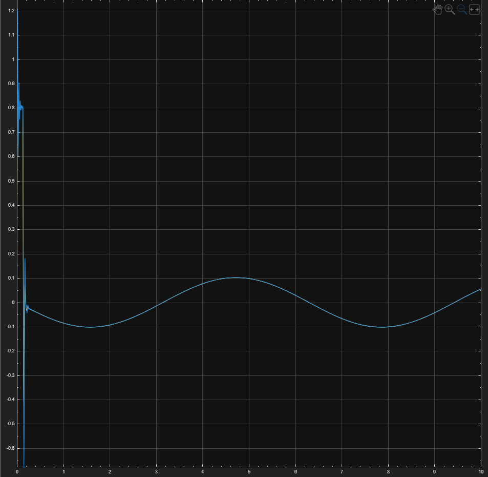
This simulation is the "Proof of Concept" for the flight control software. Before we risk a 2-meter, expensive industrial airframe over the ocean, we must prove that our PID architecture works on a fundamental level. By validating the control logic on this 0.2 kg virtual model, we confirm that the system can handle the differential equations of flight—thrust vs. gravity and torque vs. inertia. Once this logic is proven stable here, we simply update the mass/inertia parameters for the full-scale 2m drone, knowing the underlying "brain" of the drone is already mathematically verified to prevent crashes.
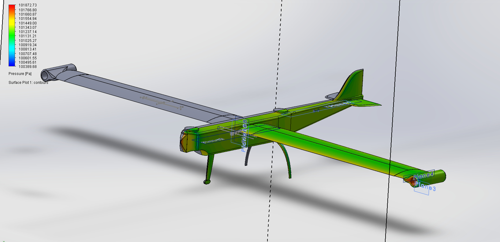
FRAME CREATION & PRESSURE SIMULATION
PROPELLER ANALYSIS
THROTTLE TILT
UAV Engineering & Design

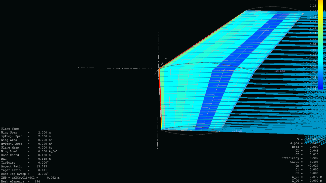

WING ANALYSIS
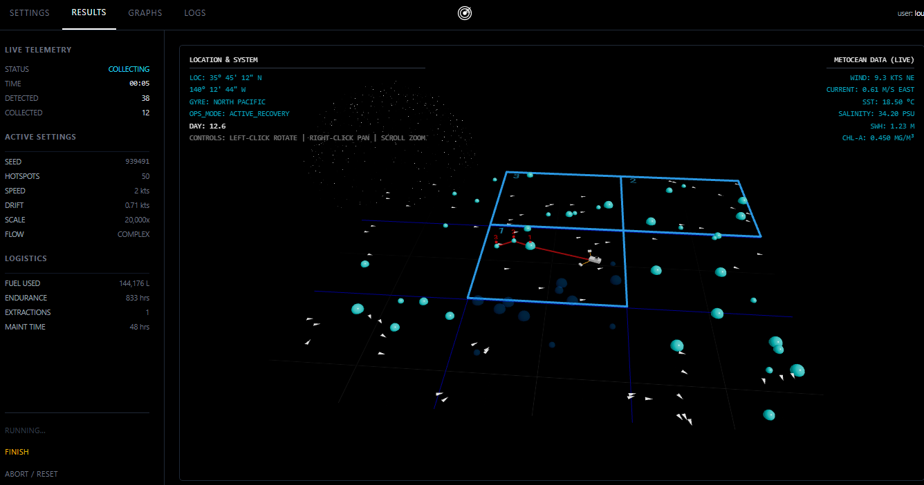
IOT Simulation

AIoT & Automation

OCELEX Route Optimisation Application


Conveyor
ANALYSIS
AI TRAINING
Workings
EQUATIONS OF MOTION AND CONTROL
CMEMS Data
